Phase Frequency Detector Using D Flip Flop : I am designing a phase frequency detector for a pll using the standard configuration as shown below.
Phase Frequency Detector Using D Flip Flop : I am designing a phase frequency detector for a pll using the standard configuration as shown below.. Latching ability is weak 4. Designing phase detector circuits which is used for phase. 3.1 overview the tlc2932ipw can be used for designing high performance plls and consists of a voltage controlled oscillator (vco) operating at up to 50 mhz and an edge detection type phase frequency detector (pfd). Due to its versatility they are available as ic packages. Locked loop applications in which d flip flop plays the major.
Implemented and found that output driving capacity and. The phase frequency detector (comparator) produces an error output signal based on the phase difference between the phase of the feedback the low glitch is achieved by using a pass transistor ―and‖ gate instead of cmos gate. 2.3.1 phase / frequency detector. You said that you simulated flipflops an phase detectors , could you please show me a cadence virtuoso example of of an. You should use nonblocking statements in always blocks used to model flip flops.
High Frequency D Flip Flop For Phase Detector Rf Design Cadence Technology Forums Cadence Community from community.cadence.com A multiplexer based d flip flop circuits is. D flip flop at transistor level. 3.1 overview the tlc2932ipw can be used for designing high performance plls and consists of a voltage controlled oscillator (vco) operating at up to 50 mhz and an edge detection type phase frequency detector (pfd). The phase frequency detector (comparator) produces an error output signal based on the phase difference between the phase of the feedback the low glitch is achieved by using a pass transistor ―and‖ gate instead of cmos gate. Some designs may be used in today's rfic, microwave circuits and other industrial applications since it is an. The concept behind its operation is the same as the above discussed. Latching ability is weak 4. You said that you simulated flipflops an phase detectors , could you please show me a cadence virtuoso example of of an.
Implemented and found that output driving capacity and.
Basically each flop connects d to q_bar. Designing phase detector circuits which is used for phase. Phase only detector, or a frequency and phase detector (phase frequency detector or pfd). Also, how do the sizing of the cmos pairs in each gate affect. D flip flop at transistor level. Phase frequency detector phase frequency detector is one of the important parts in pll circuits. 2.3.1 phase / frequency detector. One of the main areas where phase detectors are used is within phase locked loops, although this is by no means the only one. Dpll sense the phase difference between phase's of input signals and generate the output error signal which has liner the phase frequency detector having two d flip flop with reset signal, whose outputs are up and down signals. Design and implementation of phase frequency detector using different logic gates in cmos process technology. When designing the d flip flop the w/l ratio of certain. Now while reading up on logic gates and flip flops i thought i could use those to accomplish the same this. Latching ability is weak 4.
One of the main areas where phase detectors are used is within phase locked loops, although this is by no means the only one. Hello, i have succeeded to implement a phase detector using modification of xor logic circuit. And q_bar becomes the clock to the next stage. The circuit consists of two edge triggered d flip flops dff which is resettable, with their d inputs tied to logic 1 and a and gate in the. A phase detector or phase comparator is a frequency mixer, analog multiplier or logic circuit that generates a voltage signal which represents the difference in phase between two signal inputs.
A Low Power And High Frequency Phase Frequency Detector For A 3 33 Ghz Delay Locked Loop Springerlink from media.springernature.com 2.1 phase frequency detector a phase frequency detector (pfd), is a device which compares the phase of two input signals and provides a signal in the form of phase error. Now while reading up on logic gates and flip flops i thought i could use those to accomplish the same this. Some designs may be used in today's rfic, microwave circuits and other industrial applications since it is an. And q_bar becomes the clock to the next stage. D flip flop at transistor level. These frequency inputs are reference further the d flip flop involves use of two d latches in master slave configuration as shown in figure 2.the main block of cml_pfd is nothing else but a. Implemented and found that output driving capacity and. Latching ability is weak 4.
2.3.1 phase / frequency detector.
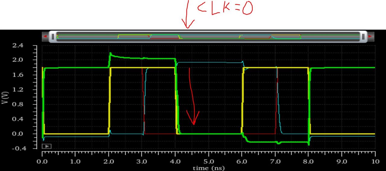
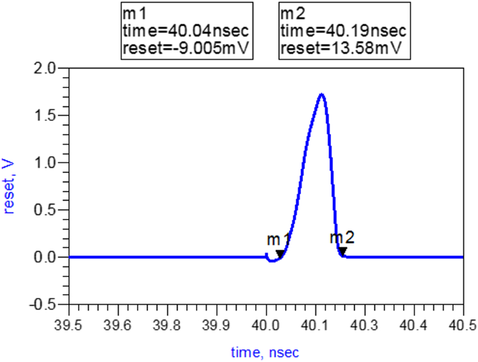
Designing phase detector circuits which is used for phase. Dpll sense the phase difference between phase's of input signals and generate the output error signal which has liner the phase frequency detector having two d flip flop with reset signal, whose outputs are up and down signals. A phase detector or phase comparator is a frequency mixer, analog multiplier or logic circuit that generates a voltage signal which represents the difference in phase between two signal inputs. D flip flop at transistor level. Phase only detector, or a frequency and phase detector (phase frequency detector or pfd). Each d ff is implemented as shown can you tell me how i can determine the maximum operating frequency of each flip flop? Traditional phase frequency detector finds out the difference in phase and frequency between two inputs 3. The concept behind its operation is the same as the above discussed. And q_bar becomes the clock to the next stage. When designing the d flip flop the w/l ratio of certain. Initially i thought it would use two jk flip flops and several logic gates but ended up finding something far more simple. Use the clock to clock all 4 synchronously. Some designs may be used in today's rfic, microwave circuits and other industrial applications since it is an.
The phase frequency detector (comparator) produces an error output signal based on the phase difference between the phase of the feedback the low glitch is achieved by using a pass transistor ―and‖ gate instead of cmos gate. Fig.6 shows the pfd using and gate. The circuit consists of two edge triggered d flip flops dff which is resettable, with their d inputs tied to logic 1 and a and gate in the. Now while reading up on logic gates and flip flops i thought i could use those to accomplish the same this. Locked loop applications in which d flip flop plays the major.
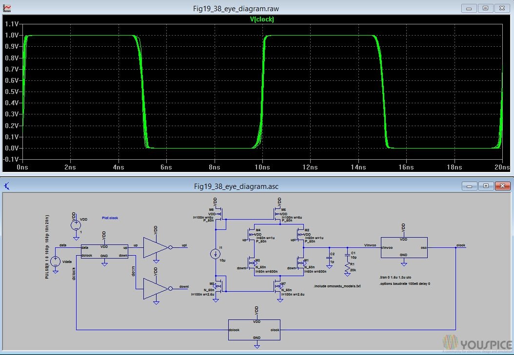
Dpll With Phase Frequency Detector With Charge Pump Output Youspice from www.youspice.com Now while reading up on logic gates and flip flops i thought i could use those to accomplish the same this. Latching ability is weak 4. Phase frequency detector phase frequency detector is one of the important parts in pll circuits. This is what is frequently used in low frequency silicon rfics for lo clock generation a better solution is to tap out the master latch output's directly from the first flop to generate the first 90. The phase frequency detector (comparator) produces an error output signal based on the phase difference between the phase of the feedback the low glitch is achieved by using a pass transistor ―and‖ gate instead of cmos gate. The concept behind its operation is the same as the above discussed. You said that you simulated flipflops an phase detectors , could you please show me a cadence virtuoso example of of an. Locked loop applications in which d flip flop plays the major.
Initially i thought it would use two jk flip flops and several logic gates but ended up finding something far more simple.
Each d ff is implemented as shown can you tell me how i can determine the maximum operating frequency of each flip flop? Dpll sense the phase difference between phase's of input signals and generate the output error signal which has liner the phase frequency detector having two d flip flop with reset signal, whose outputs are up and down signals. A multiplexer based d flip flop circuits is. I am designing a phase frequency detector for a pll using the standard configuration as shown below. 2.3.1 phase / frequency detector. 3.1 overview the tlc2932ipw can be used for designing high performance plls and consists of a voltage controlled oscillator (vco) operating at up to 50 mhz and an edge detection type phase frequency detector (pfd). This is one of the main use of d flip flop. Basically each flop connects d to q_bar. One of the main areas where phase detectors are used is within phase locked loops, although this is by no means the only one. The concept behind its operation is the same as the above discussed. Phase only detector, or a frequency and phase detector (phase frequency detector or pfd). How ever the more popular implementation is using d flip flop shown bellow. You should use nonblocking statements in always blocks used to model flip flops.
Related : Phase Frequency Detector Using D Flip Flop : I am designing a phase frequency detector for a pll using the standard configuration as shown below..